Mixing In External Sound
I need to mix pre-recorded sounds with the output from my laptop. That allows me to do sound layering and smooth transitions during laptop dead air. Running a SanDisk mp3 player into a Behringer FCV100 pedal gets me foot control of the mix-in. Running both sources into a standard mixer works fine, but makes the rig more cumbersome. My first attempt to simplify was a basic summing cable, but that got too clunky when I needed a mic level mix output for recording. My next attempt was a proper passive mixer, but the mic level attenuation wound up too quiet for the recording device I was using, so here it is with a variable pad.
Things To Be Aware Of
- The 3.5mm headphone jack on the computer is TRRS not TRS. For a Mac, the TRRS is Left, Right, Ground, Mic. You don't want the mic connection involved in the mixing at all, since amplitude fluctuations between mic and ground are interpreted as control signals, which can cause mix cutouts as the computer audio driver reacts. The cable from the Mac needs to be TRRS, going into a TRRS socket with the mic disconnected.
- The 3.5mm headphone out from the SanDisk may also be a TRRS connector. If it is, it's most likely the standard (non-Apple) TRRS configuration which is Left, Right, Mic, Ground. Again, safest to use a TRRS jack with the mic disconnected.
- Any connections of mic to ground, even on the "outputs" of this passive mixer will result in noise and could possibly trigger control signal interpretation on connected devices. Best use is to always connect using cables that are clearly TRS only with no mic-grnd connections, or clearly appropriate TRRx/TRxS cables.
Build Info
Here's a pic showing the active contacts for the pot. The center pin is
the wiper variable output. This happens to be a Taiss 1K Ohm 6 Pins Split
Shaft Rotary Linear Dual Taper Audio B Type Potentiometer, but I can't
recommend it because it makes an audible woosh when you turn it. Good
enough for a trim knob I'll adjust once at soundcheck. A 1 kΩ logarithmic
would probably be better but couldn't find one.

This is the (kinda too small) project box with the inputs and pot mounted
with lead wires. 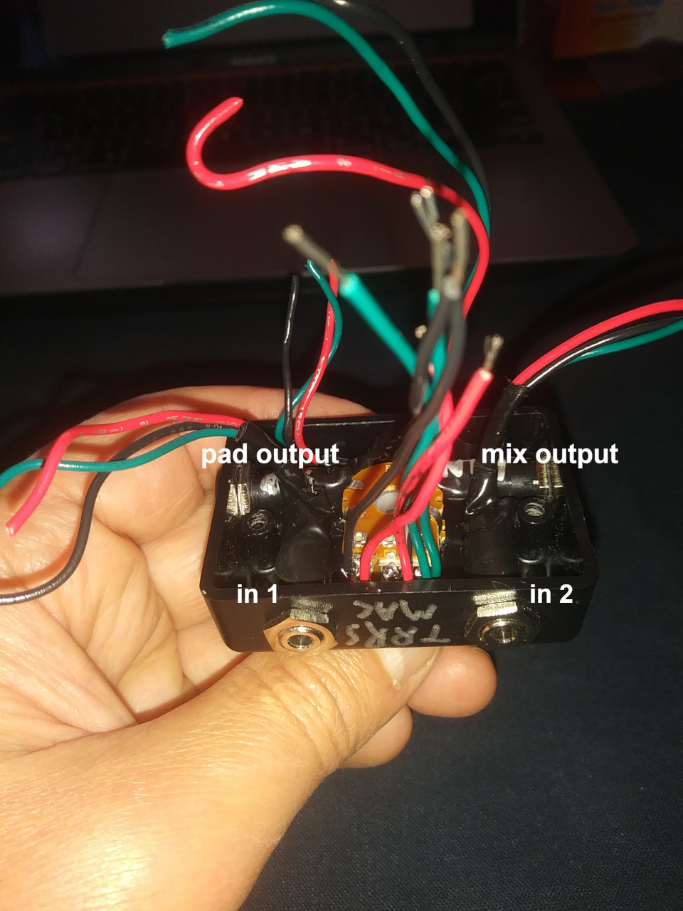
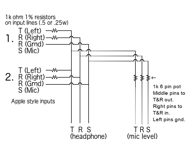
The wiring diagram for the mixer describes the connections:
Board pin map (7x8):
| BlkIn1 | --- | BlkIn2 | --- | RedIn1 | --- | RedIn2 |
| ΩIn | ΩIn | --- | --- | --- | ΩIn | ΩIn |
| --- | --- | --- | GndIn1 | --- | --- | --- |
| --- | --- | --- | GndIn2 | --- | --- | --- |
| ΩOut | ΩOut | --- | GndMix | --- | ΩOut | ΩOut |
| BlkMixOut | BlkPotIn | --- | GndPot1 | --- | RedMixOut | RedPotIn |
| --- | --- | --- | GndPot2 | --- | --- | --- |
| BlkPotOut | BlkPadOut | --- | GndPad | --- | RedPotOut | RedPadOut |
| Finished wiring. The resistors are mounted on a board with the connections fully soldered so things stay connected, and also so the connections are easy to see. Getting the project box closed was a trick but it works! | 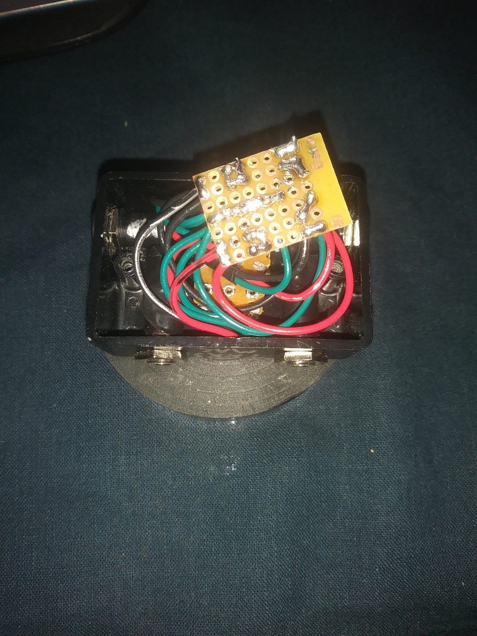 |
refs
- https://www.wikihow.com/Wire-a-Potentiometer ground the first terminal (furthest left), feed the input signal into the third terminal, and then run an output signal from the terminal in the middle.
- https://electronics.stackexchange.com/questions/24421/how-to-make-my-own-volume-control-for-headphones