Making An Audio Mix-In Pedal and Recording Tap
The need
When switching between Ableton sets, or other laptop dead air times, I want to be able to bring up ambient noise to fill the gap. I have pre-recorded sounds on a SanDisk mp3 player, which I want to blend with the output from the laptop using a foot pedal. Usually I combine the two signals through a mixer, which works well and provides more flexibility, but to travel light I want to trim this down to just a signal summing cable.
Summing Cable
It is not possible to dump the two outputs into a 'Y' plug and use the output directly. Not only do the two input signals want to fight with each other, but the laptop detects things are weird and refuses to produce any output at all. You need a summing cable, which is essentially an inline passive mixer. It separates the signals by putting each input through some resistance, allowing the signals to be combined after.
Most mixers use 10kohm resistors. That would work, but I'm trying to not drop too much gain. My friend Ennio's sound engineer friend Paul says 1kohm or 2kohm should be good for headphone output. 1k will be more gain but also more noise. 2k will be less noise and less gain. Went with 1k. Noise hasn't been an issue for me. YMMV.
The cable will be summing the left channels into a single output, and the right channels into a single ouput. The ground goes straight through. Specifically:
- left A -> 1k resistor -> left sum line
- left B -> 1k resistor -> left sum line
- right A -> 1k resistor -> right sum line
- right B -> 1k resistor -> right sum line
- ground A -> ground sum line
- ground B -> ground sum line
The easiest connections to work with are 1/4inch plugs, which is what's coming out of the inexpensive volume pedal I'm using. From the laptop it's a standard 3.5mm headphone jack. For the output, I went with 3.5mm because that's the most compatible for what I'm doing with it, even though 1/4inch would be best for pro audio. XLR wasn't good for me because which pin is hot can vary between U.S. and Europe.
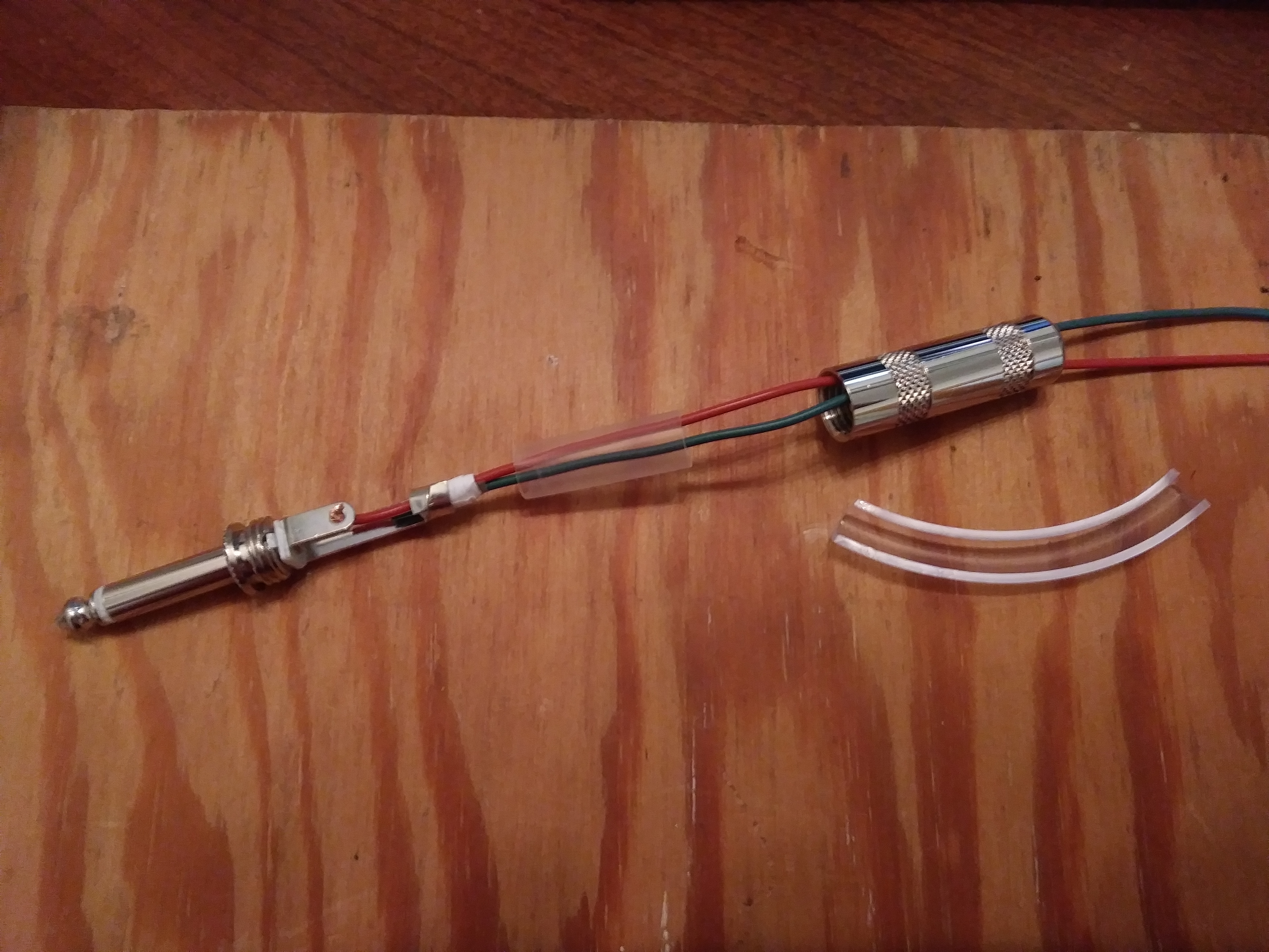
Using 20guage alarm wire since it's the most solid thing I have that will fit the 3.5mm connections, and it's nicely color coded. To add some stress relief for the 1/4inch connectors with the thin wire, I cut some PVC tubing in half and then folded it in like this:

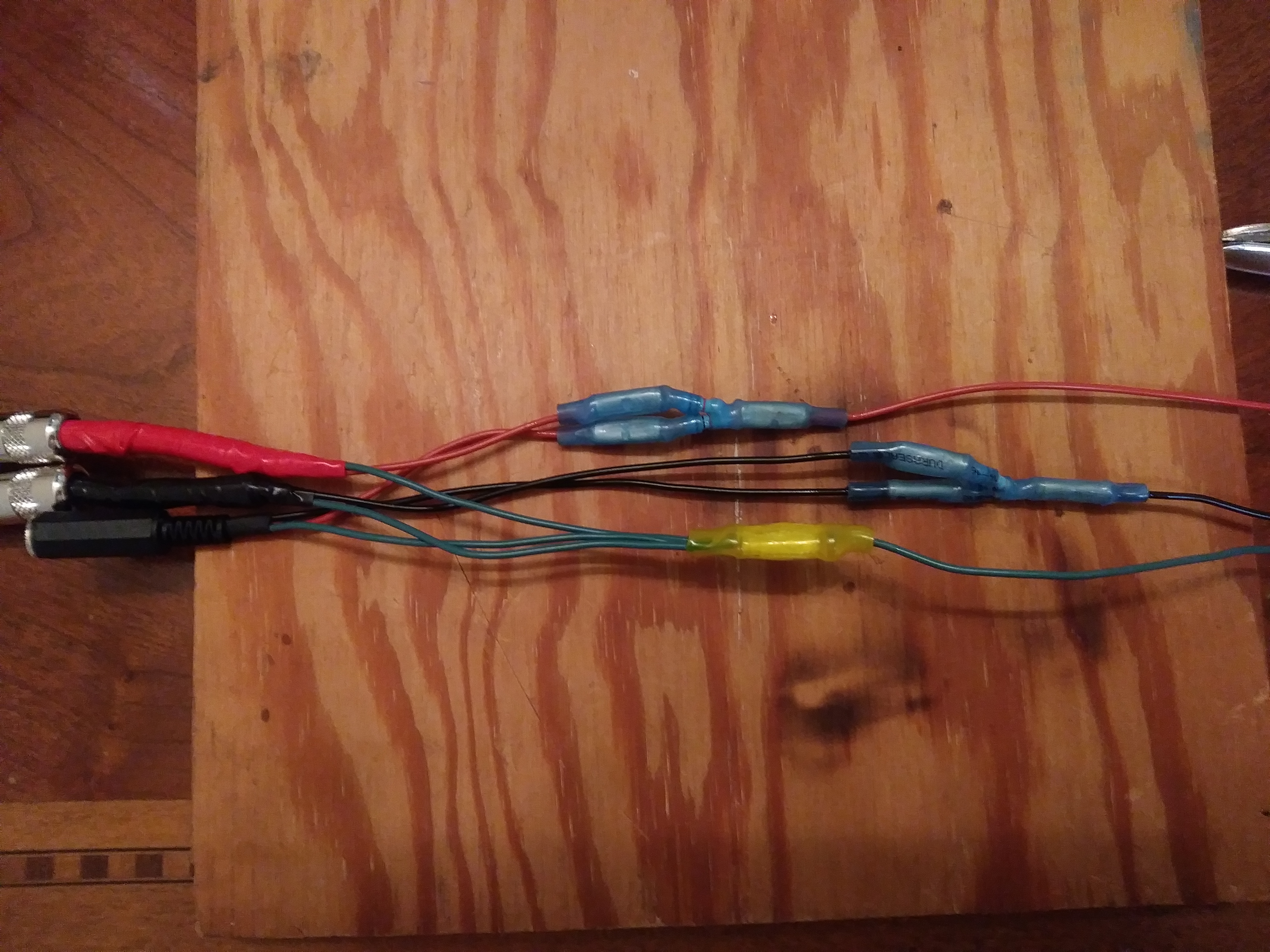
After getting the input connectors wired up and testing all the connections, I used heat-shrink butt splices to provide some structure for the resistors. Basically you crimp the splices on to make a connection, then use a heat gun to shrink the outside plastic down to provide some stress relief for the wire going in. Here's the concept, and the completed summing connections:

The resulting cable worked great! Then I realized that in my ordering haste I had used 1/2W resistors and should have used 1W for standard audio levels. Since I didn't want the cable to fail, I rebuilt it using 1W rated resistors. A bit clunkier in those summing connections but not too bad:

Unfortunately when I tried the rebuilt cable, the result was a distorted mess. Not like complete fuzzbox mess, but noticeable audio overdrive mess. I'm really not sure what went wrong, but connectivity testing showed it wasn't shorting. Possibly it was a bad patch cord, or something caught in a jack, but the upshot was I cut out all the resistors, re-tested all the connector wiring, and started to rebuild the cable yet again. But I only had the 1/2W resistors left. Found a stackexchange post saying that headphone output is typically 10-20mW. So it turns out that a 500mW resistor should actually be totally fine for these purposes. Here's the final summing cable before taping it up:
Recording Pad
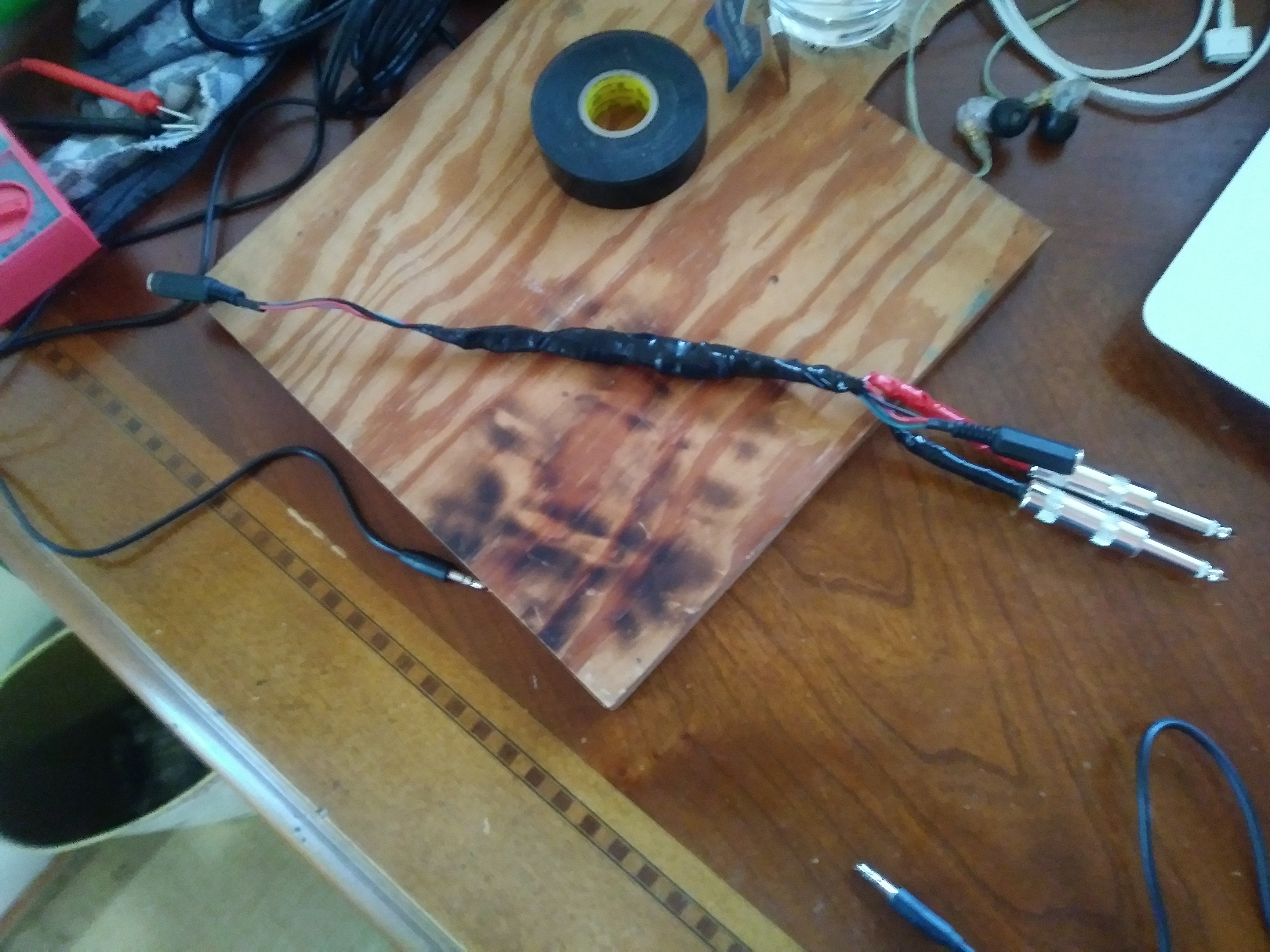
After finishing the summing cable, I realized I also wanted to be able to record the summed output. Not opening an already complex cable again, so made a 'Y' plug to split the output, and tried connecting my digital recorder off one branch with the other going to the amp. The signal was way too hot, so then I built a pad. Search for "reduce line to mic level" or similar if you want more background, the short story is that there is a 10kohm resistor on the line, then after that there's a 100ohm (0.1k) resistor connecting the line to ground. Yes, line to ground. The 100ohm resistor is in shunt, dumping signal. I wasn't sure that was going to work out, but it did. Here's the completed cable:
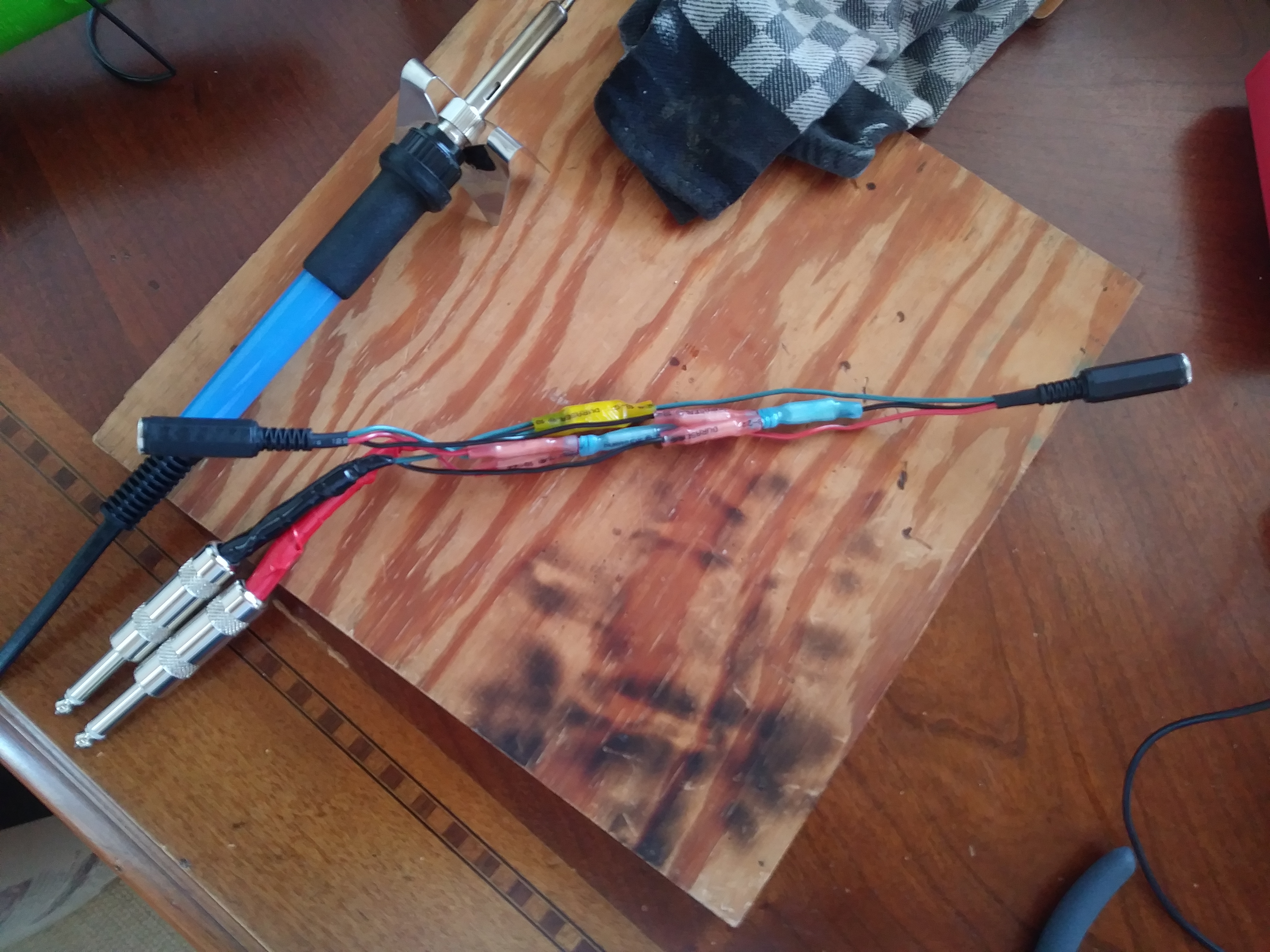
And here's an abbreviated rig showing how everything connects. You can see the SanDisk mp3 player attached to the right side of the Beringer volume pedal, and the output of the volume pedal going into the summing cable with the output from the laptop. The output from the summing cable goes into a 'Y' plug, and then from there to the amp and through the pad cable to the digital recorder.
Hope this helps if you ever want to take on building anything similar. I used lead-free solder because I like don't like working with neurotoxins. The work was completed using an inexpensive soldering iron, a heat gun, a small plywood work surface, metal pushpins to hold things in place on the board while working, vice grips, wire strippers, needle nose pliers, wire cutters, and an inexpensive multimeter for continuity testing.